Current Meters
Despite of rapid development of measuring systems based on the other principles, classic current meters with rotating propeller are, in hydrology and water management, still the most used devices for measuring of water flow velocity and discharges by the method of velocity field.
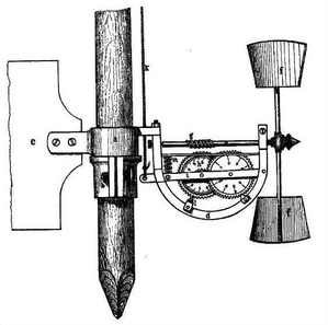
The first current meter was designed by R. Woltmann in 1787. This device had a horizontal axis and a propeller in a shape of vane wheel with two angled vanes. A revolution counter was a mechanical one and was an integral part of the meter. The device spread quickly and was widely used and improved. Especially, the shape of the propeller changed from the vane wheel into a helical screw blades (this modification was proposed by Trevianos in about 1820) which is used up to these days. R. A. Harlacher from Switzerland, professor of the Prague Technical University, equipped the current meter by an electric signaling of the propeller revolutions. The name of Ott is inseparable connected with the current meter development and production. A. Ott founded „Mathematisch-Mechanisches Institut von A. Ott” at Bavarian town Kempten in 1873. Besides other devices, this company also started production of current meters in 1875 and keeps producing them till today, although the current company name is OTT Hydromet.
A lot of types of current meters and their accessories were developed at this company and some of them went down in history – namely the “Type V” current meter and the type derived form it – “Texas”. Apart from the OTT company, there were many other producers of current meters (from the more known e.g. Amsler, Ganser, SEBA, NEYRPIC, but also the Czech Metra, several types of current meters were produced in the former U.S.S.R.) but apparently only SEBA survived up to these days. Away from these classic companies, there are many other ones producing current meters of various, often non-traditional types.
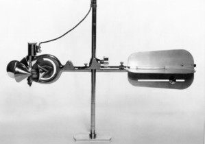
The Woltmann type of current meter is typical for the Old World. The development in the New World, namely in the U.S.A., went through other ways – American engineer W. G. Price patented his own type of a current meter with vertical axis in 1885, by its arrangement very similar to cup-type anemometer for measuring of the wind speed. The Price current meter at contemporary version (so called AA type) has a propeller consisting of six conical cups arranged on a circumference of a circle with their axes tangential to the circle. Beside of this classic type, a “pocket” current meter of Pygmy type which has smaller dimensions is used in the U.S.
 Original Woltmann Current Meter
Basic difference between both of these types of current meter is that the Woltmann type current meter registers correctly only a velocity which has direction parallel with axis of the propeller, whilst the Price current meter registers correctly any velocity regardless its direction at a horizontal plane. It has essential consequences from the measurement point of view – current meters with horizontal axis must be always set up in the direction of the water flow during a measurement, unless they have component propeller (see below). It is also stated that meter with a horizontal axis has somewhat higher uncertainties of measurement, especially at smaller velocities. The Price current meter is moreover simpler in construction. Despite of this the Woltmann meter has other advantages which make it more popular even where the Price meters prevail.
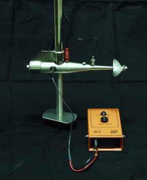
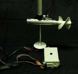
Renowned producers usually supply current meters of various sizes and with propellers of various diameters and various pitches of the helical screws so that the devices are quite flexible and usable in a wide range of conditions. Today, many of the produced propellers are so called component – such propeller registers only the component of the velocity vector which is parallel with the propeller axis even when the flow is oblique. The angle differs according to the propeller type and can be in the range of 0 to 45°. Some of the producers supply the current meters also in complete sets or it is possible to choose only selected propellers.
During the time, also the revolutions registration system changed. The original mechanical counter, forming an integral part of the meter, was replaced by electric signaling more than a century ago. Also this system developed gradually. Earlier used mechanical contacts, which gave a signal after several (even several tens) of revolution, are replaced by magnetic reed switches giving an impulse after every revolution of the propeller. This change was allowed also by a progress of an electronic – acoustic signaling devices were replaced by electronic counters which register pulses generated by the current meter’s reed switch for a predetermined time interval.
Current Meter Suspension
The current meter can be suspended either on a rod or a cable. Rods are usually folding and of total length of 3 to 5 m with single pieces of length of 1 to 1.5 m. The rods are graduated in 0.01 or 0.1 m. Ususally, there is a movable sleeve moving on the rod, which enables fixing the meter at required depth without the need to take the rod with the meter out of the water. The rod suspension is used most often in shallow streams where it is possible to wade and also when the measuring is done from a vessel or a low bridge. Suspension on a cable is usually used at deep streams or when measuring from a high bridge. When using suspension on a cable, the meter is fixed to a streamlined sinker weight equipped by a tail directing the meter in the flow direction. The cable serves not only for suspension of the meter and sinker weight, but signal cables are also led through it. The sinker weight should have a certain minimum mass given by maximum flow velocity where the sinker weight may be used. When this condition is not fulfilled, the sinker weight can be brought up to the water level by the hydrodynamic forces. Usual weights of the sinkers are 5, 10, 25, 50 and 100 kg.
In special cases (e.g. guarantee measurement of water machines like turbines and pumps), a bigger amount of current meters is mounted to a steady or movable construction. Constructions installed in pipes are steady in a shape of a cross with four or six arms according to the pipe diameter. A discharge is also often measured in a turbine intake. In this case, not only steady constructions in a shape of a grid are used, but also movable device suspended on a cable which carries one row of the current meters and moves in stop-log grooves of the intake.
Calibration equation of Current Meter
Let us have a current meter with a helical screw propeller; propeller pitch so be k [m]. The current meter is submerged in a water flow of velocity v [m/s]. It means that a water particle travels a distance v [m] in a period of 1 second. The water sets the propeller spinning and, when mechanical and hydraulic resistances are neglected, it means that the propeller executes v/k revolutions in a time period of 1 second. So that, for a known number of revolutions of the propeller N at given time t [s], the velocity is

where n = N/t [m/s] is a rotational frequency of the propeller. Because there are mechanical resistances as well as hydraulic ones, the above given equation is not valid and the dependency is much more complicated and moreover non-linear. Its exact shape and even all effects exerting influence are still not exactly known. Over time, several equations of various shapes based on more or less simplified analysis or purely empirical describing the dependence v = f(n) were proposed. Currently, the International Standard ISO 3455 prescribes a calibration equation as a per partes linear equation

where αi and βi are empirical calibration constants valid in specified range of rotational frequencies n and i is number of the linear parts of the equation, whilst i ≤ 3. The constant αi roughly corresponds to a water velocity, when propeller begins to rotate, and the constant βi is close to the propeller pitch.
The calibration equation is determined accordance with ISO 3455 on a basis of data acquired by towing the meter in a still water by a steady speed (see Calibration). During calibration, the current meter has to be mounted to the towing carriage the same way as it will be used for measurement.


