Equipment of CCSCM
Premises
Premises
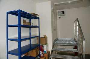
Basic premises of CCSCM are the calibration tank, control room and a hinterland with switching station from where all sluice gates are controlled.
Big Experimental Tank
The big experimental tank was built in the framework of construction of the building of former State Research Institutes of Hydrology and Water Structures and it was put into operation in 1930. The tank is fed by water from the navigational canal of the Troja weir and it passes through the area of the T. G. Masaryk Water Research Institute (TGM WRI) in a north-south direction. It has total length of 248.9 m and bottom slope. It consists of intake, equalizing part with a double sided weir for keeping the water level constant, calibration tank proper, outflow part (measuring tank) and outlet into the canal.
Intake part of the tank is situated in front (southern) part of TGM WRI area and is determined by the intake construction situated in the bay of the navigational canal in the area of upper raids of double lane one-chamber lock Troja-Podbaba and by the sluice gate I.
Equalizing part of the tank is also situated in front (southern) part of TGM WRI area and is determined by the section between sluice gate I and sluice gate II. This part of tank is equipped with two fixed overflow edges (each 25 m long) providing a stable level in a calibration part of the tank. Excess water is diverted by a separate sewer to the bottom raids of the lock. Overflow channels are on top of the normal water level of 180.10 m above sea level (altitude compensation system Baltic = Adriatic - 40 cm). Upper level of water at an elevation of 180.20 m above sea level is maintained on the Troja weir, permitted tolerances are +20 cm and -10 cm.
Calibration part of the tank is situated on the ground floor of buildings A, C and E situated in TGM WRI area and is determined by the section between sluice gate II and sluice gate III.
Outflow part of the tank (measuring tank) is situated in the back (northern) part of TGM WRI area and is determined by the section between sluice gate III and sluice gate IV. Measuring tank has length of 29 m, width of 5 m and depth of 5 m, so the total volume is 725 cubic meters.
Outlet part of the tank leads into the lower raids of the lock and is determined by the section between sluice gate IV and the outlet construction situated on the bank of navigational canal in the area of bottom raids of the lock.
All sluice gates can be operated from the switching station of the tank as well as locally, in case of emergency even by hand.
Calibration Tank
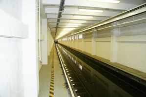
Calibration part of the tank (calibration tank) is determined by the section between sluice gate II and sluice gate III, between which the mutual distance is of 164 m. It has vertical walls, constant width of 2.5 m, average depth of2.1 m and bottom in a slight slope of 0,4 per mille. In compliance with ISO 3455 the tank is the straight open tank with volume of cca 861 cubic meters.
 Hinterland with Switching Station
Working section of the calibration tank has the length of 138.6 m and water depth of 1.8 m. In compliance with ISO 3455, this part of experimental tank comprises accelerating, stabilizing, measuring and braking sections.
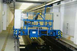
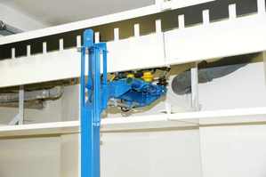
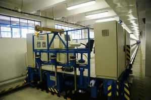
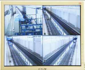
In this section the electric self-propelled rating carriage moves along the track in a speed range of 0.02 to 7 m/s. This space is an indoor one and can be heated. Along the tank, a rail track is laid for the rating carriage. The power to the carriage is fed by a three-phase trailing wire track system situated at the right side of the tank under its ceiling. A distance gauge is located at the same place. The working section of the flume is equipped by a CCTV for visual control of the carriage function during calibrations under remote control. At the beginning of the working section, a landing, used for carriage maintenance, current meters installation and other common activities, is situated. Within the framework of building adaptations after the 2002 flood, the tank was equipped by a device enabling evacuation of the carriage (which is the most valuable part of the equipment) to the Institute’s boiler room roof in a case of flood threat.
The control room was after the 2002 flood moved one floor above the tank from its original place beside the tank to the first floor.
 Images Captured and Transmitted by CCTV
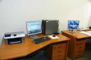
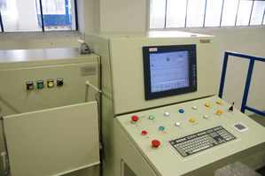
In the control room, a central computer, used for fully automated operation as well as data acquisition, their evaluation and archiving, is located. The monitor of CCTV is also situated here – the activity in the tank surrounding is monitored by 4 cameras.


